
Intermittent aeration as well as the temporization of the blowers are management strategies which can provide advantages in some common cases:
- The most common case consists of existing WWTPs which show an optimal efficiency in terms of ammonia and COD removal while having a limiting denitrification capacity, so struggling to meet the law limit for N-NO3– and/or TKN. In this context, the scheduled switch off of the blowers with the correct timing can allow to meet the outlet law limit for what concerns ammonia nitrogen providing at the same time further denitrification capacity. This could prevent the plant from exceeding the law limits, or even represent a solution to increase the capacity of the plant with a low economic effort and strong reduction of the interferences in terms of revamping interventions;
- Another case of interest concerns plants characterized by strong inlet load variations. An example are the WWTPs located in touristic areas which population can be much higher during the peak season and lower during other periods. If the plant can easily meet the law limit in terms of ammonia and COD during peak season, but it struggles to remove the nitrate, the introduction of intermittent aeration could be highly beneficial and represent a good solution to solve this issue;
- Finally, the intermittent aeration can also be beneficial in order to get energy savings when a plant is underloaded. In some cases, applying the intermittent aeration to the oxidation tanks can grant to meet the law limits even without exploitation of the denitrification capacity related to the anoxic tanks. Indeed, the anoxic fraction realized in the intermittent aeration reactors alone could provide enough denitrification capacity allowing the switch off of the mixed liquor recirculation pumps with consequent energy saving. The mixed liquor recirculation can be controlled through suitable logics to switch it on only when needed.
In terms of design it will be needed to define:
- The duration of aerated and unaerated phases on the inlet load and the law limits basis;
- Correct peak values for AOR (Actual Oxygen Request) and SOTR (Standard Oxygen Transfert Rate) during the aerated phases, and so the correct air flowrate to be provided. A proper estimation of these parameters will grant the correct design of the blowers and the diffusion system and/or the correct check of an existing aeration compartment;
- An estimation of the mixed liquor recirculation flowrate which, as already explained, could be reduce or even switched off.
WHEN IS THE SIMULATION THROUGH A SOFTWARE NEEDED TO GET RELIABLE ESTIMATIONS?
Conventional formulas implemented in spread sheets allow to define the anoxic and aerobic volumes needed to meet the outlet law limits. Let’s assume for example to have a biological volume of 1000m3 and, based on the inlet wastewater quality and quantity, to calculate the need of a 400m3 anoxic section referred to a configuration with pre-denitrification followed by an oxidation compartment. The ratio between this anoxic volume and the total biological volume can be assumed as the anoxic fraction needed in an intermittent aeration applied to the whole biological volume. Therefore, in this case it could be assumed that, providing diffusers to the whole base surface of the biological volume, the blowers can be switched off for 40% of the time and working for remaining 60%. Of course, the mixed liquor flowrate has to be maintained at high value (in the formulas) in order to reproduce the turbulent diffusion of the nitrate forming during the aerated phases. As already stated, this approach can be considered essentially correct in the above-described context but can lead to heavy errors when it comes to estimate the effect of the intermittent aeration applied to a “hybrid” configuration (Figure 6), i.e. a scheme in which the intermittent aeration is implemented only in the oxidation tank while the pre-denitrification section keeps on operating in anoxic conditions (which imply to not provide the pre-denitrification tank with diffusers).
WHY?
The reason why the conventional calculation methods are not suitable for the estimation of a “hybrid” intermittent aeration process, consists on the difficulties to figure out the nitrogen mass balance. In a “hybrid” configuration must be considered that nitrate is produced and removed in the same intermittent aeration reactor (in which nitrate spreads all over the volume through turbulent diffusion), but a part of the nitrate is also recirculated to the pre-denitrification tank. Through the above-mentioned calculation method, both the mechanisms (the recirculation and the diffusion of nitrate) have to be simulated at the same time with only one state variable (the mixed liquor recirculation flowrate), leading to a wrong reproduction of the mass balance, and so to a wrong value of the anoxic fraction to be performed in the intermittent aeration tank. The direct consequence is a wrong estimation of the AOR, SOTR and air flowrate and thus a wrong design of the whole aeration compartment.
Also in this case, implementing an ASM through a simulation software is the key to overcome the simplifications and so the errors introduced through the conventional calculation methods. In fact, this approach allows to specifically reproduce the plant configuration and the related transport phenomena, granting the results reliability. In this manner it is possible to simulate the alternance of aerobic and anoxic phases only in the oxidation tank, implementing the management logics through the controller module (Figure 8) and thus getting a reliable estimation of the length of the aerobic and anoxic phases as well as of the optimal value of the mixed liquor recirculation.
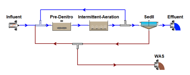
Figure 6: example of hybrid configuration in which the intermittent aeration logics are implemented only in the oxidation tank maintaining the pre-denitrification volume in anoxic conditions
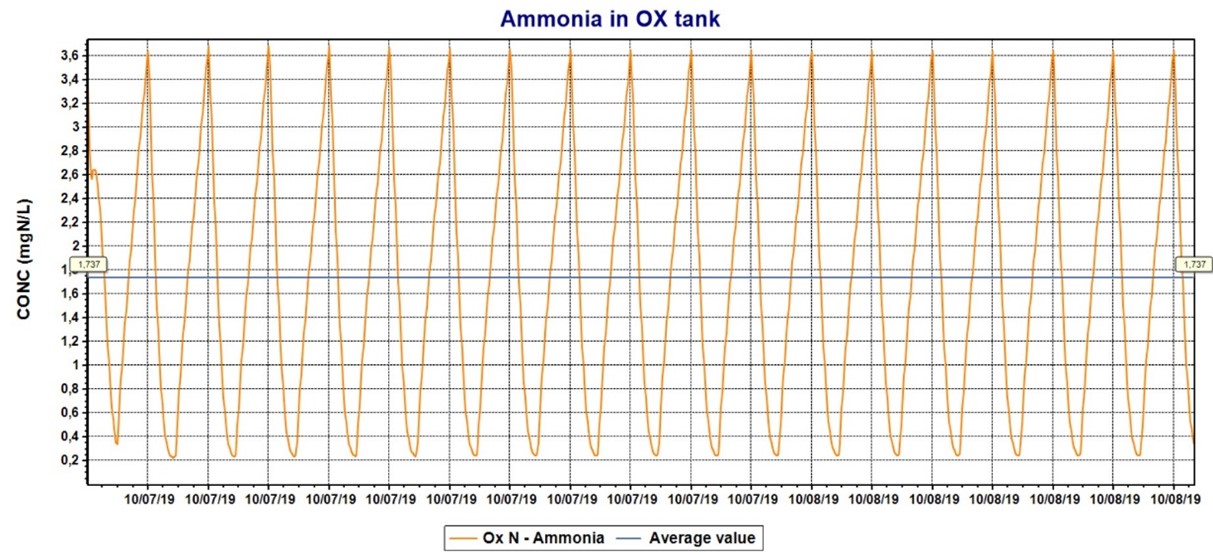
Figure 7: example of dynamic output in terms of ammonia concentration variation inside the intermittent aeration reactor
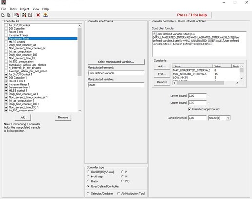
Figure 8: screen shot of the controller module integrated in the simulation software
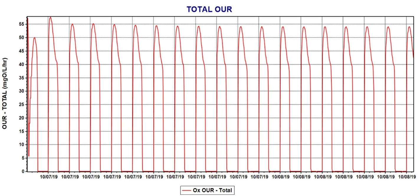
Figure 9: example of model output in terms of OUR (Oxygen Uptake Rate) in an intermittent aeration reactor treating a constant load